В этом руководстве мастер-самодельщик расскажет нам, как спроектировать и изготовить часы с механизмом из дерева. Для изготовления таких часов мастер использовал следующие
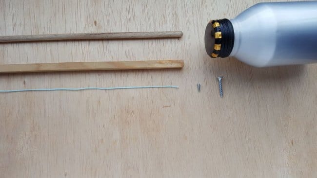
Инструменты и материалы:
-Фанера;
-Крепеж;
-Дюбель;
-Нить;
-Дрель;
-Фрезерный станок с ЧПУ;
-Надфили;
-Наждачная бумага;
-Столярный клей;
-Ножницы;
-Отвертка;
-Ножовка;
-Бутылка;
-Компьютер с ПО;

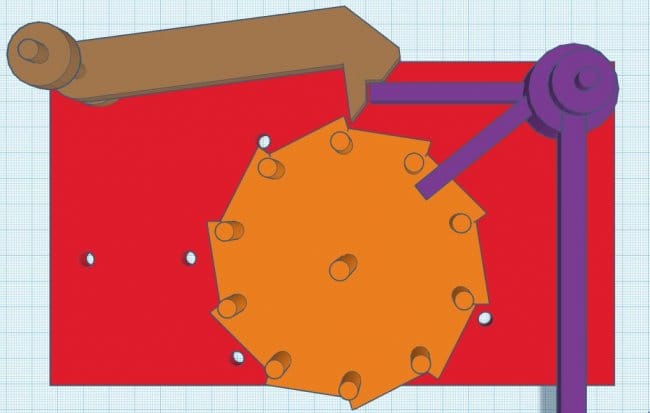
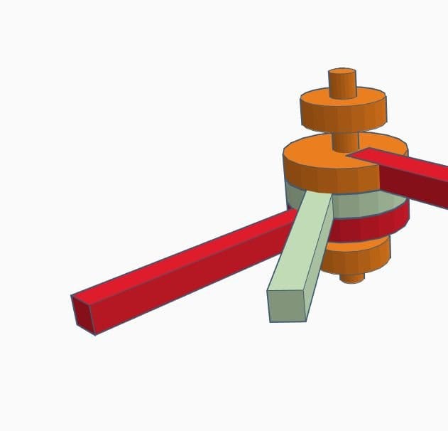
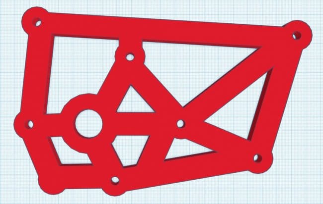
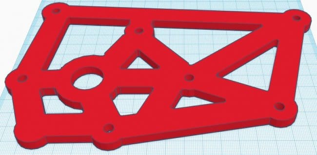
Шаг первый: проектирование
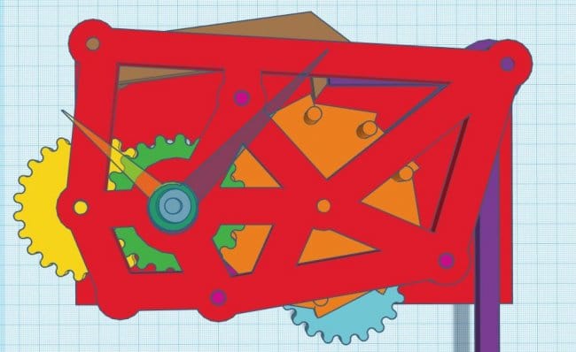
Всю разработку часового механизма мастер сделал в программе Tinkercad. Tinkercad – это бесплатное и простое в использовании приложение, для создания 3D-моделей и превращения их в настоящий продукт простым, увлекательным и интуитивно понятным способом.
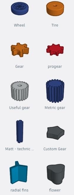
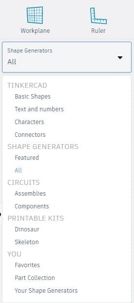
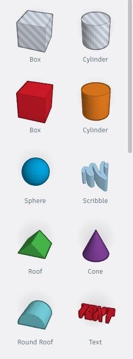
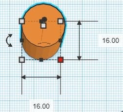
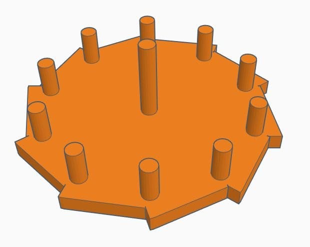
Все начинается с выбора необходимой формы. Есть несколько способов сделать это, Basic Shapes (базовые фигуры) и Shape Generators (генератор фигур).
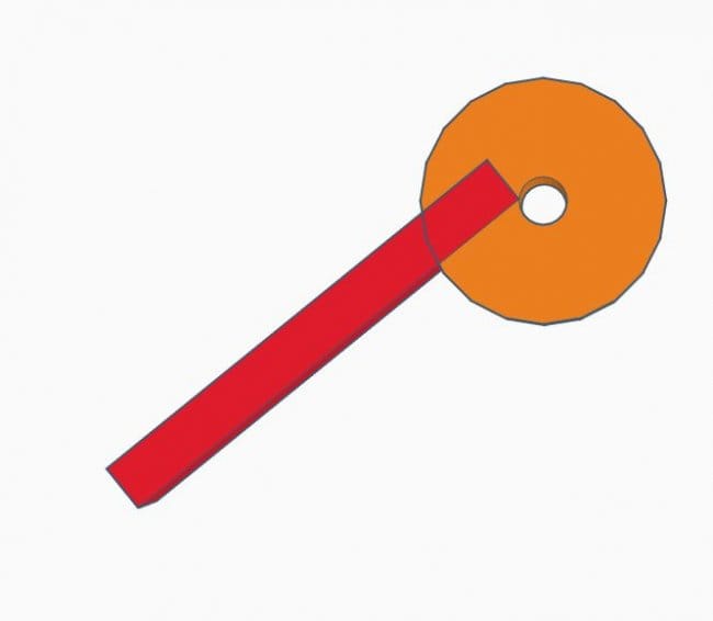
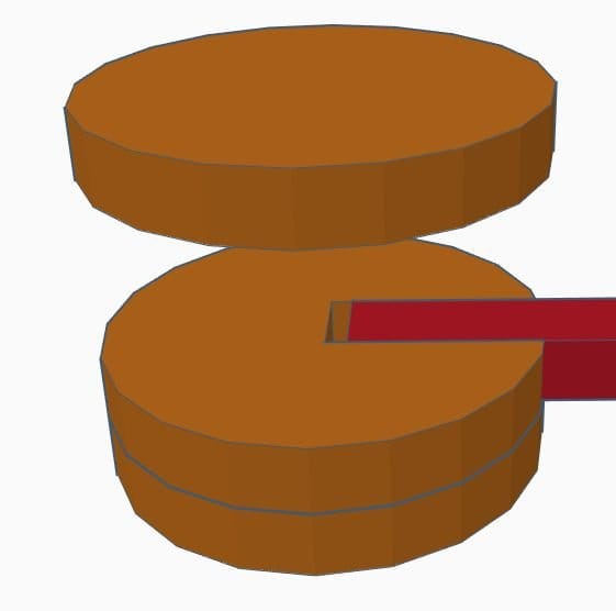
Базовые фигуры – это примитивные фигуры (Коробки, Цилиндры, Сферы), эти фигуры можно комбинировать друг с другом для создания практически чего угодно.
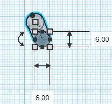
Генераторы фигур позволяют быстрее создавать сложные фигуры. Вы можете найти пружины, изогнутый текст, шестерни.
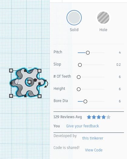
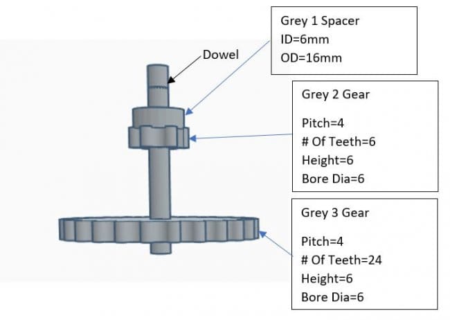
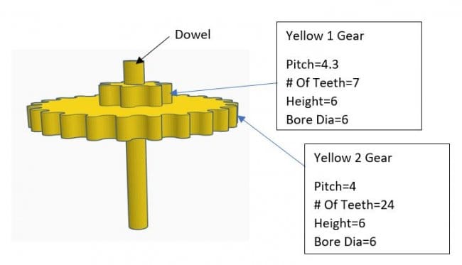
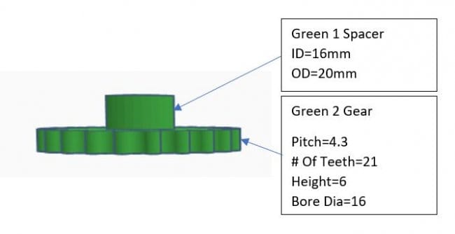
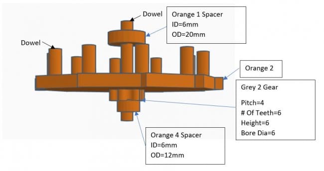
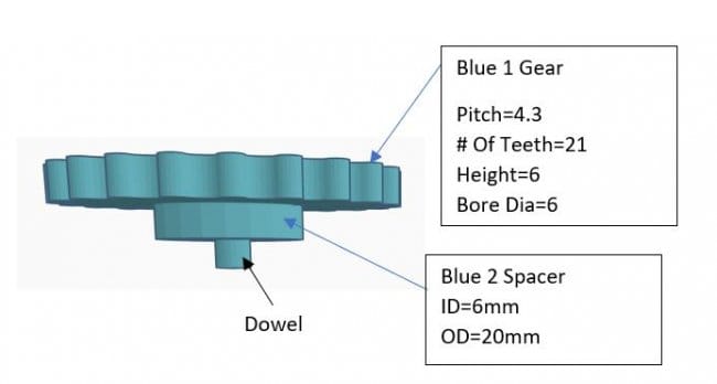
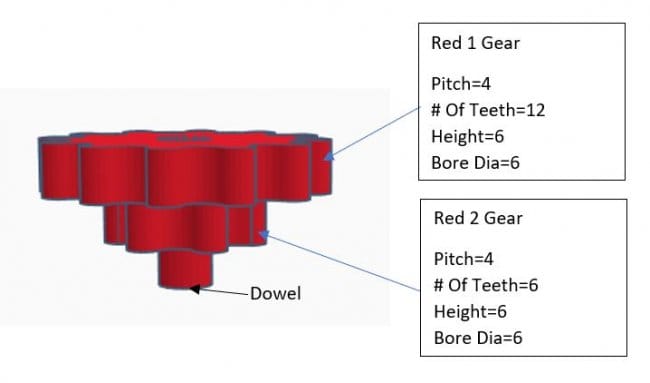
Зайдя в В> ALL> Shape Generators можно изменить фигуру. Поместите механизм на рабочую плоскость. Чтобы изменить свойства шестерни, нажмите на нее во всплывающем окне. Можно изменить шаг, высоту и количество зубьев.
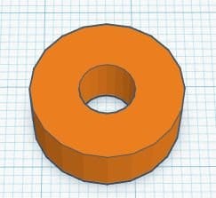
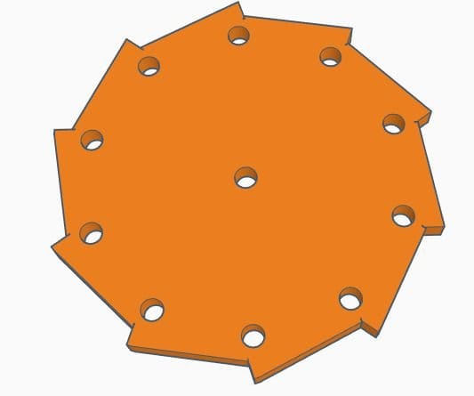
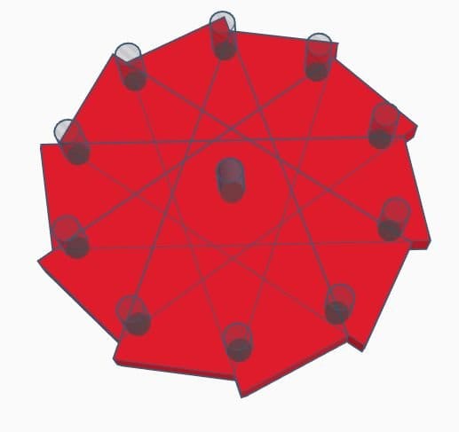
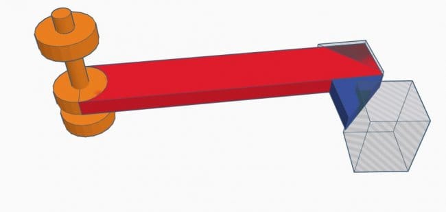
Некоторые фигуры нужно совмещать. Чтобы сделать это, нужно разместить фигуры в нужном порядке. Для изменения размера, дальше нужно выделить цилиндр, затем нажать белый квадрат на одной из нижней части цилиндра и изменить его длину и ширину. Белый квадрат, в верхней части цилиндра, изменит свою высоту.
Используя выравнивание, мастер выровняю обе части по центру.
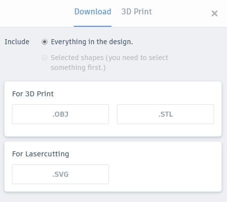
Скачать файл можно здесь .
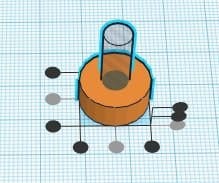
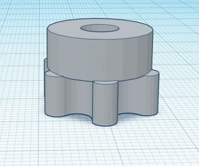
Шаг второй: резка деталей
Вырезать детали можно вручную или с помощью ЧПУ-станка. Мастер вырезает частично на станке, и дорабатывает вручную.
Welcome to Brian Law’s wooden clocks
Free plans to help you build a wooden clock. The plans on this site are those of clocks designed by myself over the last few years. At present there are Twenty one sets of plans available, and it is intended to add to them as new designs become available.
Each clock design is illustrated with a series of rendered images, and a set of drawings, drawn to scale and presented as PDF files. The earlier clocks were originally drawn to scale so that the prints could be attached directly to the timber and a band saw or scroll saw used to cut around the profiles. Now it is more common to use some form of CNC machining to produce the gear profiles, so the DXF files for the clocks are available and in some cases the 3D model files as well.
The original clocks are still available for free but as the new clocks appear I will make a charge for the files. I should emphasise here that I do not send printed copies of the files, I only supply the files so that you can either print them out yourself or use DXF files to machine your own parts.
I hope you find your visit to the site rewarding and if you have any comments or suggestions please contact me. If you would like to receive occasional newsletters about new clock releases then use the Subscribe button above.
What do I need to build a clock
This question is looked at in detail in the latest article in the Woodenclocks Blog
The article focus’s on the tools and equipment needed from the minimum, on to the requirements of a well equipped workshop.
DXF files available
If you require the DXF files for any of the clocks on the site then go to the page for the clock that you require, where you will find the DXF files listed along with model files for the newer clocks. The files can be used to produce Gcode so that you can machine the profiles on CNC machine
It is difficult to get a sense of the actual size of the clocks just looking at the pictures of them on the clocks own page. To try to overcome this and give you a proper sense of their relative sizes I produced a graphic that shows them all lined up at the same scale over 4 separate pages. Click above to download the PDF file.
All Clocks together

Scrollsaw Woodworking Magazine
3 of the Woodenclocks designs have been reproduced in the Scroll Saw Woodworking magazine. Clock 11 was the first to appear and then Clock 2 in spring of 2014 and finally Clock 17 later the same year.
The patterns and instructions provided by the magazine are excellent and will be sufficient to enable you to cut out all of the components to build the clock.
Each bundle contains the Drawings as a PDF file and the DXF files for machining and they cost $36.
Clock 33 -Has been designed to be made using almost all, Laser or CNC cut components. It is based on an old clock designed by William Strutt, in about 1830, and it has several interesting features. The foremost of these is the large Epicyclic gear drive featuring gear teeth on inner and outer parts of the ring, resulting in a rather unique design.The clock was very difficult to make at the time and few were ever actually produced, so, I have adapted the original design so that it can be hung on the wall and be weight driven instead of the original spring drive. This and the adoption of conventional gearing to achieve the 12:1 ratio for the hour hand, instead of the Ferguson Paradox gearing used on the original has made it much more practicable proposition for a wooden clock design.The large Epicyclic gear causes a few problems for the builder as it needs to be held accurately in position on the shaft so that it engages with its Planetary gear and the stationary Sun gear in the centre. To ensure this will happen all the gears on the main shaft have machined bushes to mount the gears on squarely and securely so a lathe is going to be needed to make these parts.
Although this is not really a clock for the beginner it is actually a great project if you are an experienced engineer and want a quick build and a satisfying result.
Is the first design to incorporate the Woodenclocks Gravity escapement along with a Compound pendulum. The Gravity escapement originally developed for Clock 20 has been a consistently reliable mechanism and has been running most days since built. The design is based on a design by James Arnfield with refinements to the unlocking mechanism and the moving of the Pendulum and the Gravity arm to a common pivot. The inclusion of the Compound pendulum offset to one side makes the clock more compact and more visually interesting.
It has been a while since I designed a clock using imperial units, not since Clock 25, so this one uses inches for all primary materials, although like most other clocks it is Dual dimensioned.
I have also included a separate listing of all the proprietary items with McMaster-Carr numbers to make sourcing of these parts easier.
If you would like to purchase the DXF or DWG files for CNC machining and the full unrestricted Drawings in PDF format for use with a scroll saw then go to the BUY NOW button.
I have designed this clock for my young great grandson, with a Knights and Castle theme. I have revisited the Spring powered clocks once again to allow the clock to be placed on a cabinet or shelf with none of the hanging parts that young fingers can grab and pull on. The coloured version shown elsewhere in some of the illustrations is optional.
I have for the first time experimented with a mix of materials for the build, the prototype being constructed with wooden frames front and rear, with the rest of the flat parts being 3D printed so the colour could be incorporated without additional finishing processes, designs and the instructions cover both methods of construction so whatever your choice build you are covered.
The spring drive is the same as I used on the earlier clocks and the video for Clock 14 shows how to fit the Spring into the case . https://youtu.be/Jiw4SPPkl0w
I really like this clock it runs for 10.5 hours on a single wind, it measures 41 cm high x 22 cm Wide x 170 cm deep.
This the second 3D printed plastic clock to feature on the site, it makes use of the latest 3D printing technology to offer a technically exiting challenge to the many users of this equipment. It has been kept quite small to fit within the limited size envelop of many of these machines and is designed specifically to avoid the use of supports during the printing process.
The clock features a standard gearing arrangement to give 1:120 reduction required between the driving shaft and the escapement. It has the latest Woodenclocks gravity escapement which features reduced friction within the escapement to give you a more accurate timekeeper. It also uses a gravity ratchet arrangement to make winding easier, just pulling down on the counter weight will rewind the clock to run for another 12 hours.
The clock can be adjusted to keep it running to an accuracy of 1 min in 24 hours, and maybe even better, but I gave up trying to improve on it at this point. Adjustment is by moving the pendulum Bob up or down to either speed up or slow down the clock.
Many of the parts have been split into 2 or more components to reduce the need to add supports during the printing of the part. Liquid solvent bonding is used to glue all the necessary parts together.
Clock 31 – Beginners Clock No 3 with non round gears
Clock 31, the third of 3 Beginners clocks, is again based on the same principles that links them all, and that is they are designed such that all the complicated cutting work is carried on the CNC router, you won’t need a lathe or Milling machine, just simple hand tools.
I wanted to make this one a little harder to build as it was the third in the series so it was designed with non-round gears, that is a feature of a couple of the more complicated clocks available on the Woodenclocks website. This clock whilst made simpler to build using the unique snap together shafts, needs more care when it comes to the assembly of those shafts into the Back Frame as they need to be carefully lined up so the mating gears mesh together at the right point. The gears are marked with small dots to achieve this, but if you miss them out you will be in trouble.
The majority on the Clock is made from wood in both 6 mm and 12 mm thickness, along with 2 mm ground rod or drill Rod, with the clock hands and Pallets being cut from Plastic sheet.
I have used a 500 ml Coke bottle for the weight as it is a convenient way of adding weight to the clock and provides an easy way of adjusting the weight by either adding or removing liquid. I had to actually add some extra weight to the bottle to make it up to 800 grams consistently. This has always been a problem with the Non-round gears as it creates a constantly changing torque.
The clock will run for about 8 hours and you should be able to get it to run within 1.0 minutes over that time, may be even better.
Clock 30 – Beginners Clock No 2
Clock 30 , the second of 3 Beginners clocks, is again based on the same principles that links them all, and that is they are designed such that all the complicated cutting work is carried on the CNC router, you won’t need a lathe or Milling machine, just simple hand tools. This clock, whilst similar to Beginners clock 1 has some refinements that endeavour to make it little more elegant. The gears have more delicate webs and the gear shafts have a 4-rod construction that provides strength and rigidity. This approach looks more slender than the previous clock, whilst being slightly more difficult to construct. This simple construction for each shaft ensures that the gears are held rigidly perpendicular to the shaft axis, and requiring only the CNC machined parts and the shafts to be cut to length.
Another feature of the Beginners clocks is the simple winding arrangement, with a single cord wrapped one and a half times around the drum, with a bottle of water as a weight and a couple of large nuts as a counterweight.
I have used a Coke bottle for the weight as it is a convenient way of adding weight to the clock and provides an easy way of adjusting the weight by either adding or removing liquid.
The clock will run for about 8-9 hours and you should be able to get it to run within 1.5 minutes over that time, may be even better.
There was a time, not so long ago that I could remember the details of all my clocks, but sadly there are now so many that it becomes progressively more difficult to do that. So if I am having trouble remembering details of all the clocks I realised that it must be twice as hard for you to make choices of the clock you want to make for yourself.
With this in mind, I have put together a chart that tries to list all the relevant information about each one so as to make your choice a little easier.
The chart is actually a PDF file that was created in Excel with each clock listed down the first column and the relevant feature information in the following columns.
For a full description of the chart look here
Clock 36 has been designed from the outset to run for 24 hours, so a single wind is all that is needed to keep it running all day. There are other clocks in the range that will run for this time but only if incorporating a simple pulley, in this clock the gear train has been designed to achieve this with no extra complexities.
It is a relatively simple and compact clock to construct using a high ratio gear train to reduce the number of gears required, but still maintaining that typical wooden clock mechanical appearance.
It is small enough to be cut on most CNC machines being 340 mm tall and 200 mm wide and can even be 3D printed if required.
The appearance is slightly quirky as the top of the front frame is offset to give a better view of the Graham escapement working on the large escape wheel, and for the first time in a while I have incorporated a Seconds hand that actually turns the right way without extra gearing.
This Starter clock is something a little different as it comes with an E-book as a PDF file not only gives the plans and files for you to build the clock yourself but also gives you guidance on how to design your own clock.
It is called the Starter clock because it has been designed to be built by a first time builder who has a limited amount of equipment to start the project with. It is still not an easy project because the working parts need a certain level of accuracy to work properly. You will need a Scroll saw or a CNC router to stand a chance of getting the project finished but you won’t need a Lathe or a Milling machine.
The clock itself has a simple gear train and a Graham Escapement with adjustable Pallets along with a Seconds Pendulum. For winding the clock a pull cord is used to lift the weight back up using a gravity ratchet system.
The E-Book has comprehensive instructions for making and assembling this Starter clock, as well as links to a couple of videos available on YouTube to help you as well.
All of the flat parts for the clock can be cut from 6 mm thick plywood, the files are laid out on two plywood blanks 500 x 375 mm and apart from the plywood and some 2 mm plastic sheet that is all you will need for the flat parts. A few proprietary items need to be purchased, like the steel shafts and screws but these are all listed on the plans.
The bulk of the book concentrates on looking at the details of how a clock works, its different components and details on how to design them, the gear train is looked at in more detail so that you can understand how gears are used to accommodate the requirements of different Escapement and pendulum types.
As the book covers most aspects of creating the clock parts it also comes with instructions and files for building the clock by hand by CNC and by 3D printing.
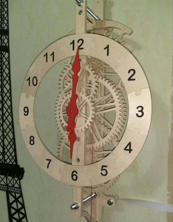
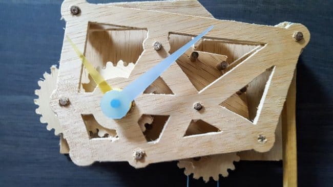
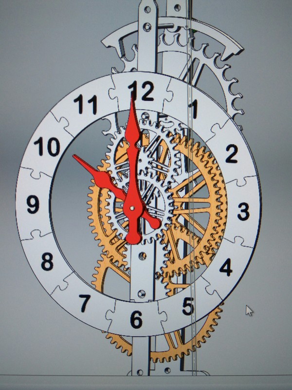
Однажды, друг прислал мне картинку часов, в которых все зубчатые колёса были выполнены из дерева, как и сами часы. Я подумал, что было бы здорово сделать такие же самостоятельно.
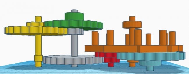
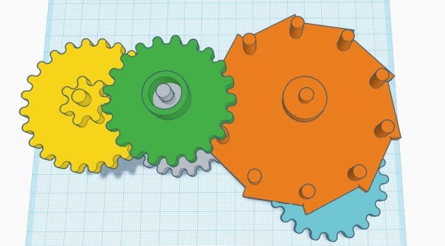
Изучив интернет обнаружил, что есть пара иностранных сайтов с чертежами. Везде всё, разумеется, платно. Самое важное, что было на этих ресурсах — картинки самих часов. Кинематическая схема была, в большинстве случаев, одинаковой. Осталось только набросать 3Д модель, сохранив нужное передаточное соотношение между колесами. За основу взял две, наиболее приглянувшиеся взгляду, схемы. Получилось вот так:
Частично из подручных средств, частично из покупных на али, собрал станок ЧПУ. Фото выкладывать не хочу, чтоб не позориться) Станок давно хотел построить для модельных дел, в последствии он не раз пригодился для всяких поделок:)